
More testing and improvements
- Andreas
- Mar 24
- 2 min read
In order to test and further improve the algorithm, another test flight took place on February 22. Our partner MSW Aviation ran through several collision scenarios with a Cessna C150 Aerobat (HB-CXQ) and a Votec-322 (HB-YLA). Both aircraft had 2 modified XC Tracer Maxx II installed, running the OCAP algorithm with the ADS-L radio protocol. Although these devices do not have an external antenna and were mounted in the cockpit, the radio link between the devices worked relatively well and the radio packets were received by each other at a distance of several kilometers. Raw data on the flights (IGC files, GPS raw data) as well as intermediate and final results of the calculations for the collision warning were recorded on all devices, as were the ADS-L radio packets sent and received.

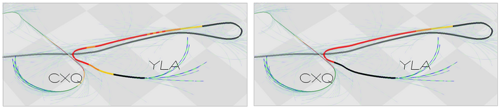
Using the recorded data, we were able to check that the calculations “on board” matched the simulation. To do this, we extended the simulation environment so that recorded ADS-L radio packets can be played back and used for the calculation in the simulation environment. The following figure shows the calculations based on the recorded ADS-L packets on the left and the calculations based on the flight paths reconstructed from the IGC files on the right. The results are in good agreement.
(Note that the alarm state based on the recorded packets (left image) is smoother than what the simulation predicts. This is due to the fact that the software in the Maxx II implements a sensor fusion and filtering algorithm on the sensor data before providing it to the OCAP algorithm.)

In a debriefing with one of the test pilots, we defined further test cases for the next test flight. We will also try to issue the alarms acoustically during these test flights. We have developed a filter for this as the “AlarmService” module. In particular, if “only” the classic ADS-L version 1 is used without our proposed Z-vector extension, the alarm level can fluctuate greatly from second to second due to the jitter of the velocity vectors (see image on the right side above). The filter in the AlarmService contains a braked decay of the alarm. In addition, the alarm is suppressed if the aircraft move away from each other, even if the calculation results in an overlap of the flight paths. The following graphics show the effect of the filter in the simulation environment. The image on the left shows the direct output of the algorithm (AlarmState objects), while the image on the right shows the result filtered by the AlarmService.


We will provide an update on this Blog as soon as we get the results from the test flights.
Comentarios