In order to generate collision warnings, the OCAP algorithm extrapolates the flight paths of the own and of nearby aircraft into the future (extrapolation) and checks whether the own and a nearby aircraft come closer than a defined minimum distance at a future point in time (warning criterion).
We defined a relatively simple warning criterion at the start of development, knowing that this would have to be adapted later. The criterion comprised fixed distances depending on the extrapolation depth (time in the future):
During our tests in recent weeks, we have found that the criterion does not generate reliable warnings.
Even a revised version with frustoconical zones did not work reliably. Although we were able to optimize the zones for a specific test scenario and achieve good results in the simulation, the parameterization had to be adjusted again in the next test in order to obtain satisfactory warnings. We therefore investigated this issue in more detail and plan to implement the approach described below.
In the following graphic, we see a horizontal extrapolation of our own trajectory from left to right. At the time of the calculation, we are at the first, thickly marked point on the far left of the trajectory. Points 1, 2, 3 etc. correspond to our extrapolated position in 1, 2, 3, ... seconds. In addition, two extrapolated trajectories of nearby aircraft that are on a collision course with us are drawn from bottom to top (red lines). The blue arrows are the distances between our own extrapolated position and the position of the neighboring flying objects at specific points in the future. There is a risk of collision with the first flying object in 5 to 6 seconds, with the second in 11 to 12 seconds.
We carry out a worst-case analysis. Depending on whether we want to generate an alarm to at least one single point or to two predicted points, we must set a different lower limit for the minimum distance. In the worst case, this distance corresponds to the long side length of a right-angled triangle whose shorter sides are given by the speeds of the aircraft (vA, vB).
If at least one point is to generate an alarm, the worst case is such that the extrapolated paths intersect at right angles exactly between two extrapolated points. The minimum distance at both points is then sqrt( (vA/2)^2 + (vB/2)^2 ).
If at least two points are to generate an alarm, the extrapolated trajectories intersect at right angles in such a way that one extrapolated point falls exactly on a point of the other trajectory. In this case, the minimum distance is sqrt( vA^2 + vB^2 ), i.e. exactly twice as large as in the first case.
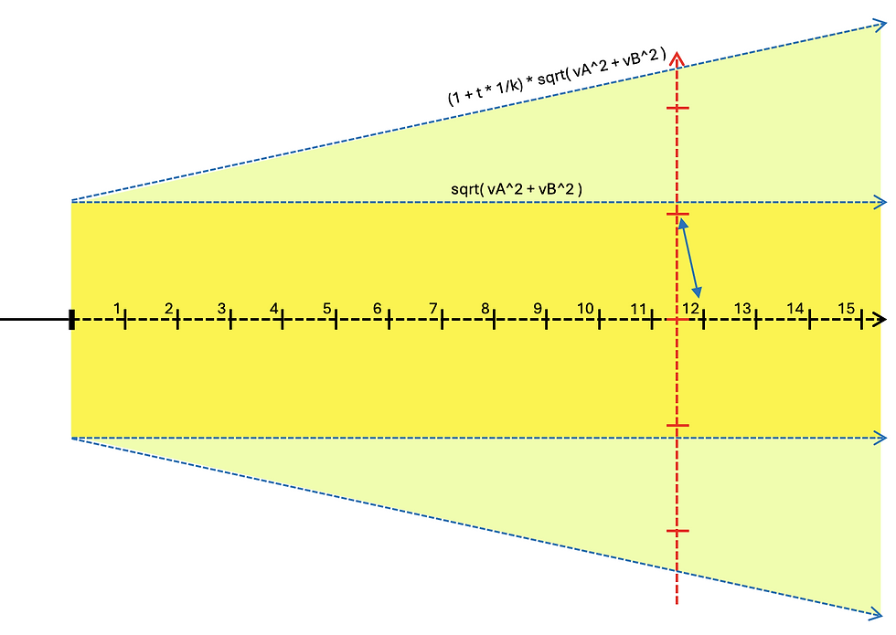
The two distances are shown in the graphic as a yellow (case 2) or orange (case 1) rectangle. These rectangles define the zones in which extrapolated points of neighboring aircraft trigger an alarm from the perspective of the own aircraft.
For safety reasons, we will continue with case 2 (two alarm points).
The further we extrapolate the trajectories into the future, the more uncertain the predicted positions are, for various reasons:
- The calculations themselves contain inherent inaccuracies, e.g. due to rounding errors or reduced resolution of values for optimization purposes.
- The measurement data (positions, speeds, directions) contain measurement inaccuracies.
- Even if the pilots want to maintain the flight path, physical influences can cause deviations depending on the flying object.
For these reasons, it makes sense to increase the minimum alarm distance with increasing extrapolation depth. The following diagram shows what a linear increase in distance, parameterized via a constant k, could look like (green-yellow area). K is defined in such a way that for k=tMax the distance at the end of the prediction is doubled (e.g. k=30 for tMax=30 seconds). The smaller k is selected, the greater the increase in the minimum distance for the alarm threshold.
An alternative would be to allow the minimum distance to grow disproportionately. We will examine this in more detail later.
In the above description of the alarm criterion, we have only differentiated between “alarm” (minimum distance not reached) and “no alarm” (minimum distance not reached) for the sake of simplicity. In the implementation, we will of course again take the originally defined 3 levels of alarms (low, medium, high) into account. The description refers to the highest alarm level. For the lower levels, a multiple of the described range is used (e.g. factor 2 for level 2, factor 3 or 4 for level 1).
Next, we will incorporate the described adaptation into the algorithm and use the test cases already carried out to check and parameterize it appropriately. We will then carry out further tests in practice.


Comments